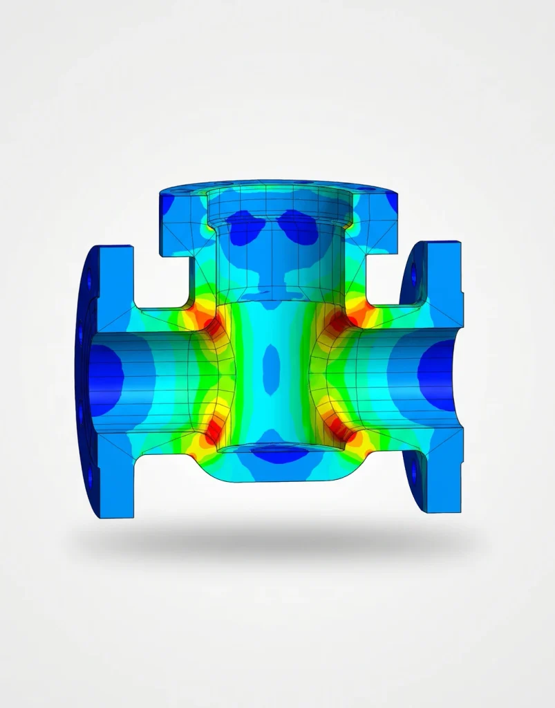
A choke and kill manifold looks like a dense cluster of valves, chokes, and pipe spools, and sizing one properly means working through several interlocking decisions at once — pressure rating, choke sizing, redundancy, and line routing — each of which constrains the others. Here’s what actually goes into that.
Start with the pressure rating the manifold has to hold
The manifold’s working pressure rating is set by the maximum anticipated surface pressure (MASP) for the well — the highest pressure the system could see during a well-control event, not the normal producing wellhead pressure. This drives the API 6A pressure class for every component in the manifold, and it’s deliberately conservative: a manifold sized to normal flowing conditions and then asked to handle a kick is sized to the wrong number entirely.
Choke sizing: the part that actually controls flow
The chokes themselves — typically one adjustable and one fixed, plumbed in parallel — are what actually throttle flow and hold backpressure during a well-control circulation. Sizing them means working through the same critical-flow logic covered in our Choke Bean Sizing calculator: given an expected kill-circulation rate and gas-liquid ratio, what choke size holds the target backpressure, and does the resulting flow stay in the critical (sonic) flow regime the sizing correlations assume. The difference on a kill manifold is the range of conditions that single choke has to cover — from the start of a circulation with a kick still in the wellbore, through to clean kill-weight mud, which is a much wider operating window than a producing choke ever sees.
Redundancy: why there are two of almost everything
A choke and kill manifold is well-control equipment, and well-control equipment is built assuming something on it can fail mid-operation. That’s why a standard manifold carries redundant chokes (adjustable and fixed, either usable to control the well), redundant valve paths so a stuck or failed valve doesn’t isolate the whole manifold, and often duplicate pressure gauges and readouts. The redundancy isn’t excess capacity — it’s the ability to keep controlling the well if one component fails at the exact moment it’s needed most.
Line routing and remote operation
Kill lines (pumping into the well to regain control) and choke lines (flowing returns out under controlled backpressure) are routed and rated separately, since they see different flow directions and different erosion and pressure profiles during a kill circulation. Manifold valves are typically hydraulically or remotely actuated rather than manual, so the manifold can be operated from a safe distance during exactly the event it exists for — which also means the actuation system and its power supply have to be designed with the same redundancy expectations as the manifold itself.
Where these decisions interact
None of this gets decided in isolation. A higher MASP pushes every component to a higher pressure class, which affects available choke options and valve sizes; wider expected GLR variation during a kill circulation affects how much adjustable range the chokes need; and line routing constraints on a platform or pad can limit how much physical redundancy actually fits. Manifold design is fundamentally a sizing exercise across several constraints simultaneously, not a checklist applied to one component at a time.
We design choke and kill systems — chokes, valves, manifolds, and associated line connections — to API standards. See our Design & Engineering services, or talk to an engineer about a manifold design.